Rio Tinto - Kennecott Utah Copper Smelter
Please, I would love to hear from you. Do you have a favorite(s), thought or question? You can tell me what's on your mind at the end of this page. THANK YOU!

Kennecott Smelter Slag Mill 28
It is here that S slag from the cooled Kress pots is ground and prepped for use as a furnace coolant and to recover the small amount of copper still contained in the slag. Kress pots are cooled by the application of water introduced into the pot over the hot slag. Steam rising from the cooling pots can be seen in the background.

Kennecott Smelter Slag Mill 29
Another view of the slag mill.

Kennecott Copper Refinery 48
As seen from the Salt Air Recreational area near the Great Salt Lake. Steam rising from the lower right is from cooling Kress pots filled with molten S Slag and on the lower left you can see more steam rising from the water cooling baths that circulate thru the water jacketed temperature control system in the walls and ceilings of the smelting and concentrate furnaces. Temperature control of the entire smelting process is critical to a successful operation. Escaping the stack are hot steam emissions originating from all around the plant which have undergone extensive scrubbing and cleansing operations to keep pollution well within local, state and federal requirements. This image is artistically rendered.

Kennecott Smelter 53
The Smelter has 3 primary furnace operations, the Flash Smelting Furnace (FS), the Flash Concentraiting Furnace (FC) and the Anodes furnaces. Ore concentrate (roughly 27% copper content) is the primary feed material for the FS furnace wherein it is smelted into Matte Copper (68% to 70% copper) and S-Slag waste material. This matte copper becomes the primary feed material for the FC Furnace which further smelts it down to Blister copper (99.8% pure) and C-Slag waste material. From the FC furnace the molten blister copper is fed directly into Anodes Furnaces that adjust sulfur and oxygen after which it is cast into large anode plates and shipped to the refinery for final processing.

Kennecott Smelter 55

Kennecott Smelter 56

Kennecott Smelter Panorama 57

Byproduct Rail Cars 59
Rio Tinto is very conscious of its environmental stewardship, constantly pursuing all avenues available, as well as aggressively researching new methods to eliminate the smelting processes potential negative impact on the environment. Before being released into the environment all forms of potential pollution, including the steam and vapor emissions produced by the refinery are vigorously and meticulously scrubbed and cleaned to exacting standards. Pure quality sulfuric acid, held in rail cars such as these, is a byproduct of the smelting process emissions scrubbing and cleaning procedures. It is from here that it is shipped for use by many other industrial processes.

Kennecott Smelter 60

Acid Byproduct Loading Station 61
It is here that special rail cars are filled for transport.

Kennecott Copper Mine 61
Material with no value, called overburden, is deposited by huge dump trucks, capable of hauling over 400 tons of material, over the side of the mine. Consequently the roadways and landscape of the mine'e interior is constantly changing. Ore, called pay-dirt is deposited into a large crusher located inside the mine. From the crusher, ore is sent over a 5-mile conveyor belt system that runs through 3 miles of tunnel to the concentrator where large grinders further pulverized the stone into a fine powder. The concentrator takes the pulverized ore and mixes it into a slurry that is then piped to flotation cells were it is mixed with reagents to produce a bubbly froth. Copper, gold, silver and other metals adhere to the bubbles which is skimmed off and filtered. The resulting concentrate, which contains about 26 percent copper and by-products such as gold and silver, is then sent through a pipeline to the smelter for further processing.

Truck Shop and Staging Area
Of the two Bingham Canyon Mine heavy hauler truck shops shown here the smaller white building was destroyed on April 10, 2013 when more than 160,000 tons of earth sloughed off of the side of the mine (just to the right of the shop) into the bottom of the pit making it the largest human caused landslides in recorded history. Although the slide cost Kennecott many millions of dollars in lost time and equipment, it was accurately anticipated due to constant state-of-the-art geological movement monitoring technology and occurred without injury or loss of life.

Kennecott Copper Mine 63

Kennecott Copper Mine 64

Kennecott Copper Mine 65
This image gives a comparative indication at just how big the excavation of the mine is. What is pictured here on the mine wall is an unplanned movement of the stepped ridges. Although rare, such movements do occur, however, because of Kennecott's safe and efficient mining practices, ongoing training of its work force, state-of-the-art geological monitoring equipment, zero tolerance safety programs, practices and requirements, such occurrences are prepared for and safely handled. Kennecott's safety record is among the best in the industry.

S Slag Excavators 66
As the molten matte copper is tapped off of the FS furnace it is plunged into a highly turbulent water bath the causes it to become a coarse black sand like material. These matte excavators remove the granulated matte from the granulation pit and deposit it onto belts for removal to the dome or to a matte pad to be relocated by the material handlers driving large front-end loaders.

C Slag Excavator 67
This excavator is removing C-slag from the FC furnace granulation pit. Unlike the S-slag which is tapped into large Kress pots, cooled, ground and reprocessed due to remaining 2% copper content, C-slag has only a minuscule amount of copper so, like matte, it is tapped and fed into a turbulent granulation water pit and then removed by this excavator for use as a furnace coolant (among other things) to regulate furnace temperatures and chemistry.

C Slag Excavator 68

Matte Launders 70
These are 2 of 4 short water cooled portions of the matte launders that deposit the molten matte into the turbulent water filled granulator and therefore have to be cleaned (shelled) between each tap. The long heated concrete portions of the launder stretch between these sections and the matte tap hole on the floor above. Due to the need to keep the natural gas burners, seen atop the right side of the launders, away from the turbulence of the granulator, the heated launder could not extend all the way down to the granulator. The gray "crusted Over" appearance of this area is due to blow-back from the high intensity reaction of pouring hot metal onto cold water thus, over time, the blow-back will form a grayish layer over the launders and surrounding area. Heavy steel doors enclose this area and entrance is strictly forbidden during the granulation process for obvious safety reasons.

Boiler Drain Valves 71
Boiler condensates drain valves.

Molten Matte Copper 72
The bright yellow flow is molten matte copper being tapped off of the flash smelting furnace (FS). It is approximately 68-70% pure copper at temperatures well above 2200 Degrees Fahrenheit and will flow down a short heated launder into the matte granulator (see image 70) where is will be prepared to be fed into the FC furnace and further refined into blister copper with a purity of 99.8% copper.

S Slag being Plugged 73
Molten slag splash resulting from closing the slag tap hole on the smelting furnace. A soft clay plug is fastened onto a round steel plate welded to the end of a 10 foot long "Dolly" bar and shoved into the running hole using a pneumatic ram.
S Slag Plug 74
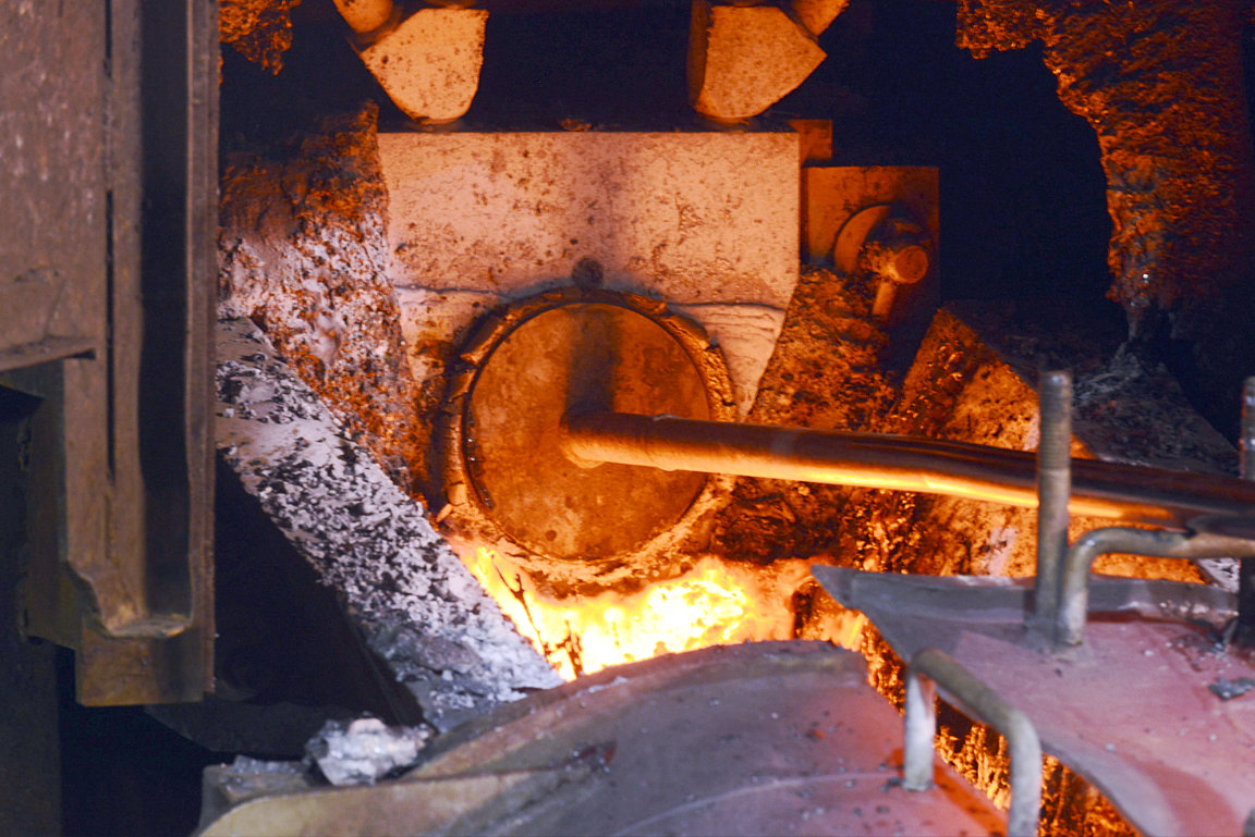
This S Slag hole has just been shut off with a soft clay plug fitted onto the end of a Dolly bar and pushed into place using a pneumatic ram. The face plate opening of the tap hole is water cooled to keep it from overheating during the tapping operation. Behind the face plate are large silicone carbide inserts capable of withstanding the high temperatures of the molten slag. Unlike the Matte, C Slag, and Blister tapping holes, these S slag holes are much bigger and do not require burning to open unless they're closed for over an hour. They are routinely in constant use, being closed only long enough to change the kress pot, and require only a pneumatic jack hammer to knock out the clay plug to restore flow. Under normal circumstances once the flow is started the molten slag flow will burn the tapping hole completely open on its own.

Molten Smelter Slag 75
A reduced flow of S Slag falling from the launder into a Kress pot. During the copper ore concentrate smelting process the matte copper seperates from the majority of impurities resulting in a floating Slag layer inside the furnace that is then drained (tapped) off into large Kress pots and transported to a cooling location. The temperature of the slag is generally about 2350 degrees Fahrenheit.

Molten Smelter Slag 76
A minimal flow of S Slag falling into a kress Pot. A kress pot holds approximately 674 cubic feet of material. At the rate of flow shown here it would take several hours to fill a kress pot. Under normal circumstances the slag flow will fill a pot in about 25 minutes and at maximum flow the kress pot can fill up in as little as 15 minutes. When full the pot will be swapped out with an empty pot and transported to the cooling area. After the pot has cooled for 96 hours the hardened slag will be re-processed to recover the 2% remaining copper content.

Blister Copper Tap 77
This is Blister Copper being tapped of off the Concentrate furnace, it is over 99% pure copper.

Blister Copper Tap 78
From here the blister copper is sent, via a heated launder, to one of two large barrel furnaces (image 111) where the oxygen and sulfur content of the copper are adjusted. A final slag content is then skimmed off by rotating the furnace and dumping out the slag for further processing. before being cast into large anode plates, loaded onto train cars and sent to the refinery.

Matte Tapping Operation 79
The tap holes are sealed with a clay plug which allows the material within the tapping hole to harden. Consequently the hardened material must be burned out to allow molten material inside the furnace to flow out the tapping hole into the launder. The procedure of opening and closing drain holes on the furnace is called "tapping" and is used to maintain proper furnace bath levels. Matte tapping procedures happen, on average, 3 to 4 or more time during a 12 hour shift.

Matte Tapping Operation 80
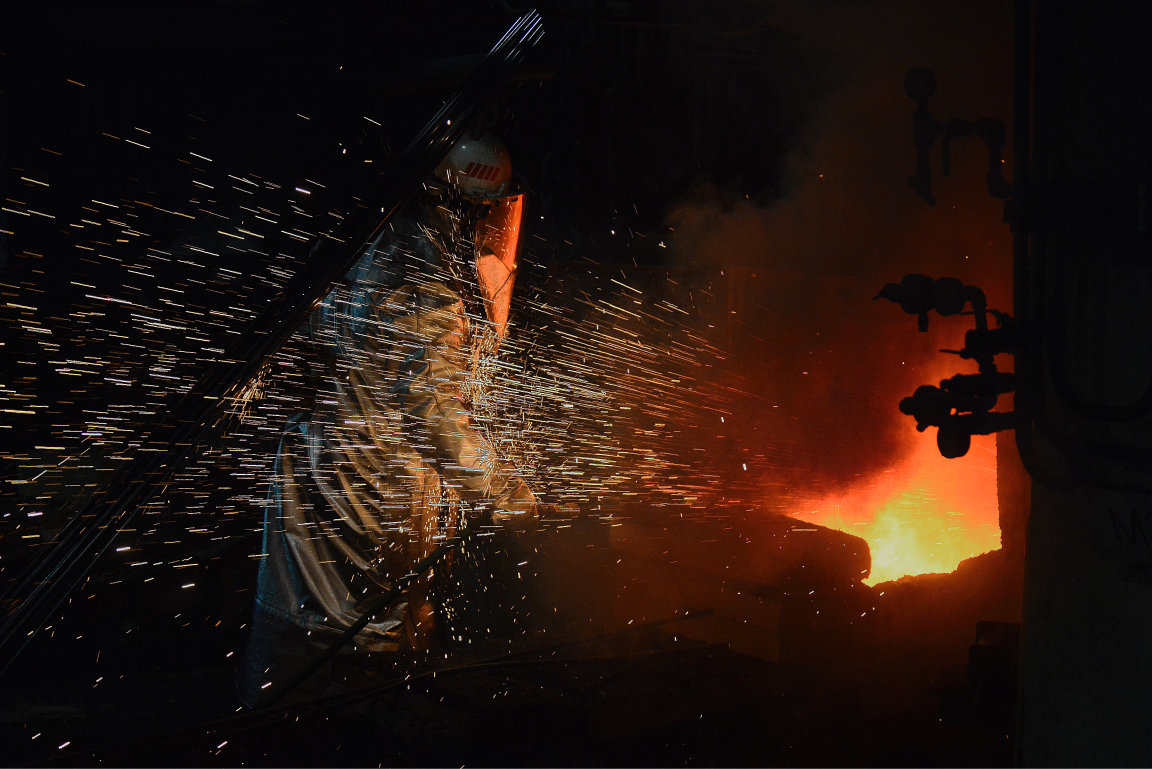
A matte tapper is burning open a matte tap hole necessary to drain smelted matte out of the furnace bath. During the smelting process inside the furnace the matte settles to the bottom of the bath where, after reaching a predetermined level (bath levels are measured hourly), it can be tapped off. The slag floats on top of the matte so consequently the physical location of the matte tap holes relative to the slag tap holes is a critical consideration in the furnace design. The furnace is routinely fed over 200 tons of material per hour so the timing of the tapping processes is extremely important to keep the bath within proper levels. Wait too long to start tapping off the matte and matte levels will reach the slag holes, tap too long and slag will begin to flow out the matte holes. Both occurrences can cause difficulty in the process including possible lengthy shut downs of the furnace.

Matte Tapping Operation 81
To burn open the tap hole a 10' long steel tube called a lance pipe (you can see them leaning next to the tapper) is attached to a coupler that feeds pure oxygen into the tube. When the end of the tube is exposed to the intense spark generated by the igniter box (seen on the right side of the image) the oxygen ignites and the tip of the steel lance begins burning at extremely high white hot temperatures consuming the lance as it burns thru the slag.

Matte Tapping Operation 82
The lance pipe is then fed into the hardened tap hole which melts out the plug and restores material flow from the molten bath inside the furnace. It takes several lance pipes to burn open a tap hole.

Launder Burners 83
The smelting operation uses specially constructed concrete troughs called launders to flow molten material from one location to another. Natural gas burners keep the flow path (Launders) heated preventing the material from hardening as it moves through the various processes.

Slag Shankers 84
As the S slag falls into the Kress Pot the resulting splatter begins to build up on the side walls of the enclosure. The results are large "shankers" that must be knocked off of the walls by hand using long steel poles plunging the shankers into the pot.

Granulated Matte Excavator 85
After being tapped off of the furnace the molten matte copper is fed into a swiftly tabulating water bath. Due to the sudden differentials in temperatures caused by dumping molten matte into cold highly tabulating water, extreme build ups of pressure in the matte material and subsequent intense releases of energy are produced. This extremely energetic reaction is very well contained in a completely enclosed heavy thick walled concrete granulation pit. The result is a black material resembling coarse sand which is then excavated out and is used as feed material for the concentrate furnace where it is further refined into blister copper.

Granulated Matte Excavator 86
The excavator removes the granulated material from the Granulator bath and conveys it onto belts that carry it to the next step in the process which is either to the Dome (see image 125) or to a matte pad where material handlers remove it to be stored until it is needed.

Furnace Natural Gas Lines 87
Natural gas is mixed with oxygen to fire the furnace reaction shaft.

Furnace Natural Gas Lines 88
Burner air/gas manifold

Tapping Gear 89
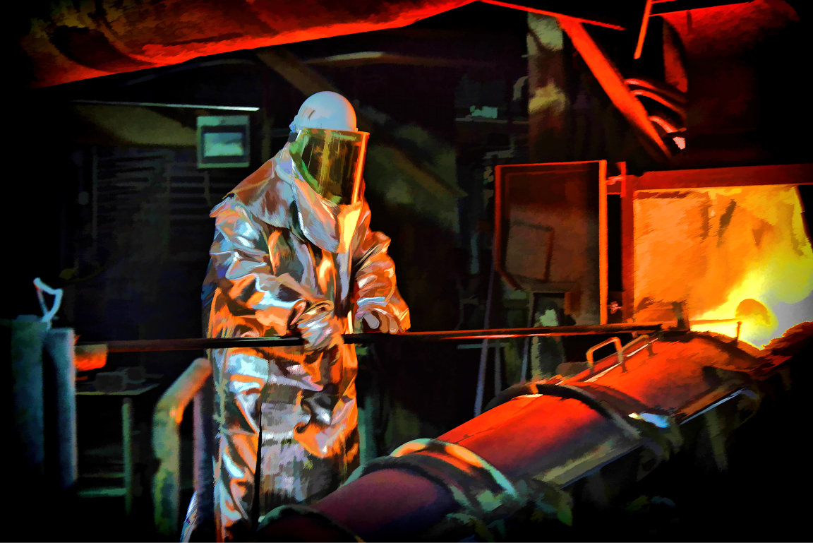
Kennecott and its parent company, Rio Tinto, takes the health and safety of its employees very seriously. Regardless of cost the best personal protection equipment (PPE) available is used and replaced without question if worn out or damaged. The heavy aluminized leather tapping gear shown here completely protects the tapper from head to toe from the heat and molten material splatter. A full face mask respirator is worn under the face shield. The proper use and care of all necessary PPE is vigorously enforced, there are no exceptions to this rule.

Tapping Gear 90
Burning open S slag tapping holes is only necessary for holes that have been shut down for long periods of time. This particular tap hole is a back-up hole used only when one or both of the other 2 tap holes needs to be shut down or fails to flow sufficiently to keep slag at proper levels. In this image it is easy to see the hose feeding oxygen to the coupler and lance pipe. Look closely and you can see the tapper feeding a steel re-bar into the hole along side the lance pipe as "Fuel" to increase heat to the levels necessary to burn open the tap hole. This procedure produces a fireball at the end of the lance pipe that exceeds 5000 degrees Fahrenheit. Behind the tapper is a dolly bar loaded with a clay plug to close the hole when needed.

Renewing a Matt Tapping Bowl 91
Because of material accumulation in the matte and blister tapping bowls and concrete launders (those that are not water cooled) they need frequent maintenance to clear the build-up and renew the path. Employees of an independent contractor are constantly at work keeping the bowls and launders clean. Water cooled Slag launders are kept clean by the tappers.

Sun and Steam 100
Sunlight gleaming through steam generated by the granulators.

Closing a Matte Tap 101
To close a matte tap hole a clay plug is fastened onto the end of a dolly bar and lightly hammered into the open hole using a rapid and very precise tapping technique after which the material itself quickly hardens inside the hole to form a very secure plug that must be burned out to open the hole again. If the dolly bar is struck too hard or improperly once the plug is seated the plug will quickly fail. That is why a second prepared dolly bar is always close at hand.

Measuring C Slag Tamperature 102
The temperature of the molten material is taken using a single use disposable thermal-couple fitted to the end of a reader. When inserted into the molten stream a light metal protective cover is melted away exposing a delicate ceramic tip with the thermal-couple wire inside.

Molten Slag Cascading into a Kress Pot 103

Molten FCF Slag 104
One of three C slag tap-holes. Unlike the S slag tap holes the C slag tap hole must be burned open every tap because it is opened only prior to a blister tap which occurs only 3 to 5 times in a twelve hour shift. This allows the hole to harden sufficiently that simply knocking out the clay plug will not start the flow.

Blister Tapping Ports Artistically Rendered
Three of the eight blister copper tapping bowels and launder that have had the build-up removed, cleaned, prepped and are ready for tapping. The blister launder is not water cooled and is covered with furnace brick to insulate it against the loss of the heat provided by the gas burners. When ready for tapping operations the inside of the launder under the brick is glowing a bright yellow hot. The white padding is a very dense fiberglass material resembling compacted cotton or wool and is capable of withstanding temperatures in excess of 2500 degrees without disintegrating.

Slag Launder Build Up 106
Keeping the slag launders free of buildup is a constant chore for the slag tappers. Because the slag launders are water cooled slag will start to harden along the edges of the flow and build up over the top creating tunnels thru which the slag will flow. Many factors can determine the frequency and difficulty level of removing this buildup called a slag shell. Things such as slag level in the furnace, chemistry, mineral content and temperature determine the viscosity and "stickiness" of the slag which, in turn, determines the rate of flow and how quickly a shell builds up. On average the launder lids must be opened once every 3 or 4 pots and the launder quickly cleaned, most often while the slag is still running. A 6' long steel bar known as a skym-bay bar is used to break up the shell so the flow can wash it into the Kress pot. If the shell is heavy and/or hard or the flow is not sufficient to move it when broken up, such as you see here, the shelling must wait until the hole is closed whereupon the launder is "dry shelled" because the shell becomes brittle when cooled and is easier to break up and push into the pot.

Working The Hole 107
Slag tapper using a skym-bay bar to dress the S slag tap hole.

Opening S Slag 108
Tapper using a jack hammer to open an S slag hole.

Shelling the S Slag Launder 109
Tapper using a skym-bay bar to shell the launder. The process of shelling entails breaking up the hardened slag in the launder so the molten slag washes it into the Kress pot.

Anodes Casting 110
Anodes casting is the final destination for the copper at the smelter after the anodes barrel furnace has finished reducing it to 99.99% purity with proper oxygen and sulfur levels (measured in parts per million). From here the cast anodes (seen hanging red hot at the left) is placed into a water bath called a "Bosh Tank" for cooling and then removed by a large forklift and readied to be moved by flatbed rail car to the refiner where precious metal is extracted, primarily gold and silver, and the copper is electrolytically refined to ASTM international standards.

Anodes Barrel Furnace 111
This is one of two Barrel Furnaces (the East furnace can be seen in the back) where the blister copper is further refined into anode copper ready for casting, it is here that the oxygen and sulfur content is adjusted. These furnaces also receive scrap material thru the large doors seen on top and from a small shaft furnace used to recycle used anodes. The round "barrel" shape of the furnace allows it to be rolled in one direction so the last remaining process slag content can be poured off leaving nothing but 99.99% pure copper in the bath after which it is rolled in the opposite direction to pour off the copper for casting.

Kress Hauler 112
On Kress road the Kress Hauler is king, they have absolute right-of-way. Other vehicles must contact the Kress Hauler driver on a dedicated radio channel and get permission to cross Kress road even if the Kress Hauler cannot be seen. All foot traffic must cross the road at one of several designated points. Radio permission is not needed for foot traffic. This image has been artistically rendered.

Kress Hauler 113
The Kress Hauler is a very specifically designed vehicle, it has one purpose, to handle Kress Pots. Not only are they designed to move them they also have the ability to raise them up and dump them out. This can be accomplished because the pots are top heavy. Once raise up the hauler starts tipping the pot hydraulically then, at a certain point, gravity takes over and the pot tips completely allowing the rim to hit the ground jarring the material out. Then the pot is pulled back into an upright position ready to be filled again.

Kress Hauler 114
Although the Kress hauling activity has an excellent safety record due to strictly enforced rules and safety regulations, driving the Kress Hauler can be a precarious activity because it transports huge pots of molten material. Drivers are very well trained and certified for many hours on empty pots before being allowed to operate a Kress Hauler to pick up and transport filled pots.

Kress Hauler 115
The Kress hauler has a steering axis on its frame between the cab section and the pot handler section. The tires are all on fixed axles. It steers by pivoting the entire cab section on the steering axis thus the Kress Hauler has a very tight turning radius. The cab has two sets of steering controls, one facing forward and one facing backwards. This allows the driver to rotate his seat facing the pot to maneuver the vehicle until a positive Kress Pot pick up has been made and then the seat is rotated back around facing forward to transport the pot.

Kress Hauler 116

Kress Hauler 117
A Kress Pot filled with molten S Slag on its way to the cooling grounds where water will be slowly bled into the pot for 3 days. When completely cooled and solid the Kress Hauler can pick up the pot and raise it up high enough to dump it onto its side and jar the solid slag out of the pot. See Image 121. This image has been artistically rendered.

Kress Hauler 118
Kress Haul Road is very well maintained to ensure a smooth ride for the Kress hauler.

Kress Hauler 119
Kress hauler exiting the tunnel where the pots are filled.

Kress Hauler 120
Here you can see the glow of a full pot on the roof of the tunnel where the pots are filled.

Kress Hauler Dumping A Kress Pot
One of the many unique features of the Kress Hauler is its ability to raise up the pot and tip it over to empty it.

Kress Pot 122
The furnaces are on the second floor. When S slag is tapped it runs down the launder and cascades into Kress pots beneath them shown here on the first floor where the Kress haulers can gain access to them. Here you can see two pots side-by-side both being filled simultaneously.

Kress Pot 123
Kress pots being filled. Artistically rendered

Kress Pot 124
Kress Pot waiting to be filled. The light is coming from the molten slag filling the pot sitting next to it.

The Mixing Dome 125
The dome is the collection point for the Matte. From here it it mixed with other materials to adjust chemistry for proper smelting and fed to the concentrate furnace. The long lighted extensions leading to (and from) the dome are covered conveyor belts.

Slag Sample 126
Sampling the various material streams is a very frequent task. The samples are sent to the Lab for analysis in order to maintain the high standard of product quality continually pursued by the smelter. The samples are drawn directly from the molten product stream and deposited into heat-sink molds for cooling. This image has been artistically rendered.

Fire In The Hole 131
Natural gas flames emanating from a matte launder into the matte bowl. You can see the plugged matte tap hole behind the flames.

The Stack 140

Anodes 142
Launders between the anodes furnaces and the anodes casting wheel.

The Hydromet 145
Processing area for liquid and slurry material streams.

The inside of the Flash Smelting Furnace (FS) 150
It is here in the FS furnace that the raw ore concentrate is smelted into matte copper having a 68% to 70% copper content. Periodically the furnace reaction is shut down long enough for inspection ports on both the FS and the FC furnaces to be opened and the interior of the furnace visually inspected. Before opening the ports the slag level in the furnace is typically drained to a level below the tapping ports, this makes starting the reaction again easier and more efficient. The 2 small dark triangular areas are 2 of the 3 slag tapping ports as seen from the inside of the furnace. When the inspection ports are opened cooler air is drawn in causing the bath to scale over and take on the dull orange color seen here, the white hot areas are portions of the bath under high intensity natural gas manage burners used to maintain interior heat levels during the inspection as well as helping control interior build up of solid material. The area inside the furnace is roughly twice that of the FC. When the inspection doors are closed and sealed again and the reaction started the entire bath becomes a molten bright yellow/white hot color reaching temperatures of nearly 2400 degrees. This image has been artistically rendered to enhance detail and contrast.

The inside of the Flash Concentrator Furnace (FC) 151
It is in the FC furnace that the matte produced by the FS furnace is concentrated into blister copper over 99.8% pure. The surface of the molten bath can be seen on the lower half of the image. The settler roof is the diagonal section in the middle while the top shows a portion of the large round reaction shaft connecting to the furnace roof. On both the FS and FC furnaces it is in the reaction shaft that the granulated feed material is introduced into the furnace along with draft (air flow) from 3 stories up and heated (smelted) to a molten state before it hits the bath. The vertical shafts of light are high intensity natural gas flames (manage burners) being injected into the furnace simply to maintain the heat levels produced in the reaction shaft and control the buildup of solid materials. There is another shaft called the uptake shaft behind this one on the north end of the furnace in which the hot draft is taken up and passed through large boilers to produce steam that is sent to the power plant to generate a great deal of the smelter's electricity. Both the FS and the FC furnaces have a reaction shaft, an uptake shaft and a boiler.

FC Furnace Drained 153
Due to an impending extended shutdown (6 or more hours) the bath here in the FC furnace has been drained down to its lowest level. Although the remaining bath cannot be seen behind the forward ridge, the light from the remaining molten material is illuminating the lower portion of the back wall. The temperature inside is still around 2000 degrees and therefore, to compensate for the high dynamic range of the image (a measure of the range between light and shadow), and bring out depth and detail, a polarizer lens and a magenta filter were used on the camera. See the FC at operating bath level, image 151, without filters applied.

Matte Tapping 154
Matte Tapping 155

Kress Pot Handling Node 160
It is these "handles" on the sides of the Kress pots by which the Kress hauler is able to secure the pot and raise it up to pivot it for dumping. The pot sits on the flat underside of the handle providing stability while transporting. The Kress pot is approximately 15 feet tall and holds over 674 cubic feet of material. This image is artistically rendered.

S Slag Tapping 170

S Slag Tapping 171
S Slag Tapping 172
Artistically rendered

Cooling Water 175
Just like the water that cools a car engine is circulated thru a radiator to remove heat the furnaces also uses a recirculating water jacket to control temperature. Cooled water is circulated throughout the furnace walls to keep the furnace from over heating after which the hot water is sent to large tanks sitting on steel structures over recovery pits. The water is cooled as it is showered from the tank into the recovery pit where it is then sent back to be recirculated into the furnace cooling jacket. The shower resembles a torrential rain but many times more dense.

Acid Plant 180
One of the usable byproducts of the emissions scrubbing and pollution abatement operations is sulfuric acid. The sulfuric acid is then processed, purified and sold to industry.

Acid Plant 181

Acid Plant 182
Pollution abatement and control compromise a very large portion of the entire smelter facility. The actual smelting process occurs on only a 4 floor section of the hot metals building. The rest of the facility is mostly material handling, byproduct production and pollution control.

Stack Interior 190
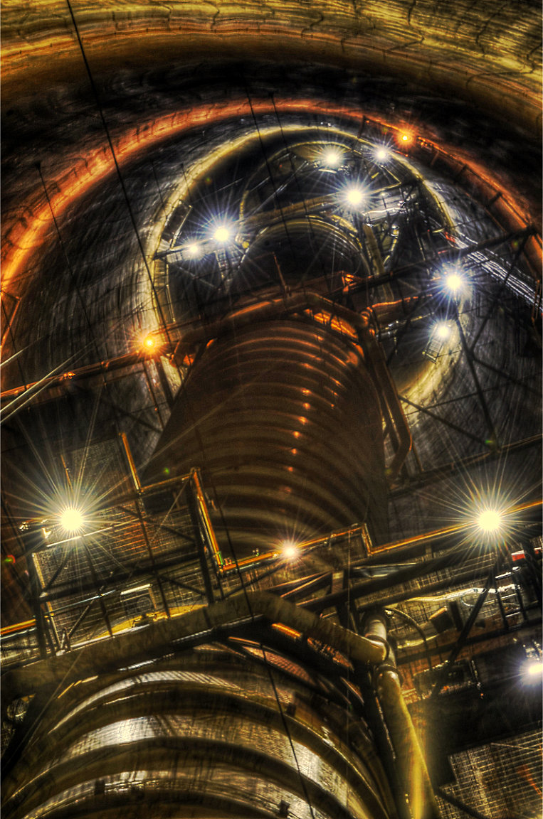
A common misconception about the stack is that it is the actual carrier for emissions when, in reality, it is only a support structure for the insulated emissions conduit seen entering the side of the stack near the bottom and rising over 1215 feet straight up to the top.

Stack Interior 191
The base of the stack measures over 177 feet in diameter and has a two man elevator that reaches various stages of the conduit ultimately reaching the top.
Stack Interior 192
Kennecott takes its environmental stewardship very seriously. It is inside the stack, at the monitoring levels accessed by the elevator, that daily discharge air quality monitoring activities are accomplished ensuring that Kennecott remains well within Federal, State and Local emission guidelines and requirements.

Outside Stack 193
Standing next to the stack wall looking straight up over 1215 feet.
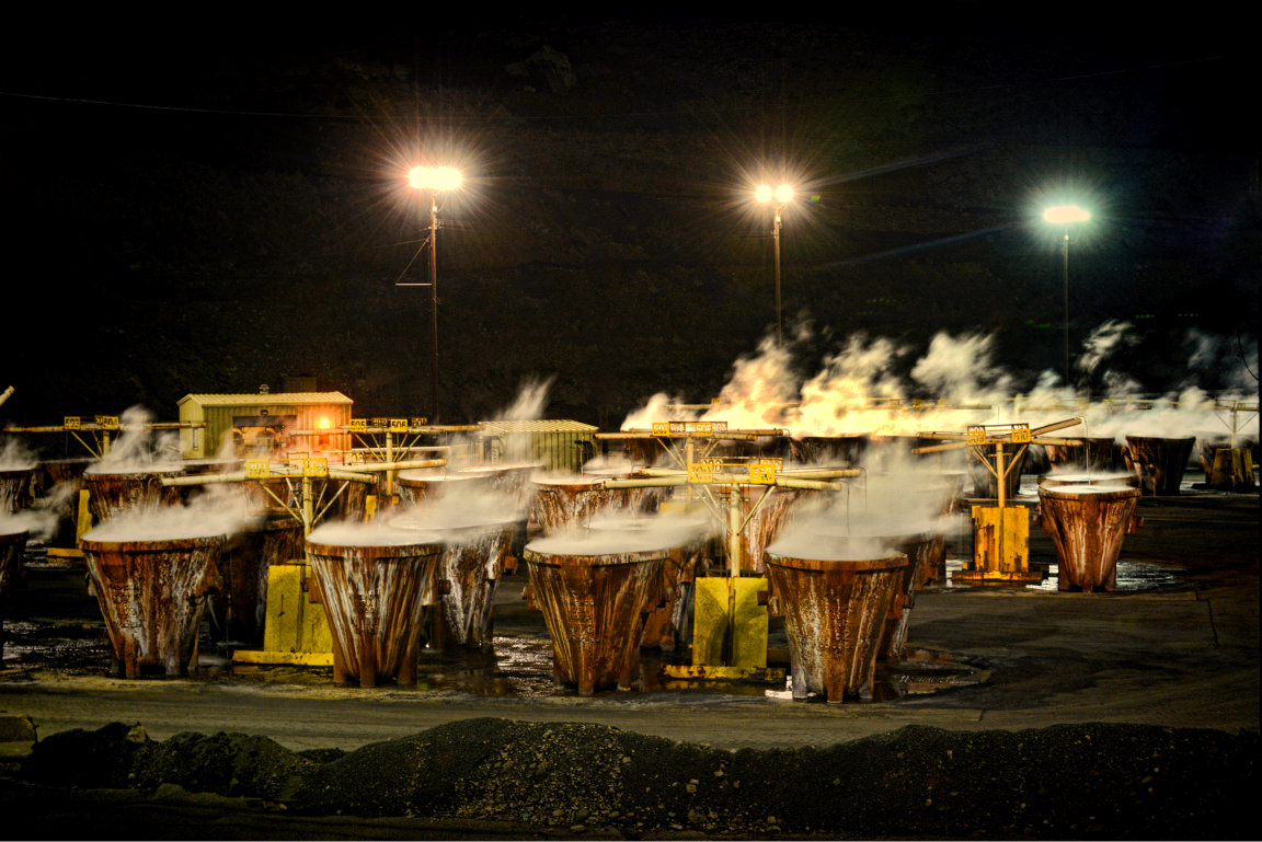
Kress Cooling Grounds 200
Kress pots in the early stages of cooling.

Kress Cooling Grounds 201
Cooling Kress pots produce a considerable amount of steam.

Kress Hauler Setting Pot To Cool 210
Filled Kress Pots are left to cool for 96 hours before being emptied and returned for refilling. The smelter has approximately 180 Kress pots

Slag Mill 220
View of the hot metals building from atop the slag mill.

Shaker Screens 229
To properly analyze certain components of the smelting process the material must be screened for uniform particle size. The material is placed in one of these pans that have screen bottoms of varying mesh sizes and then the pans are placed on a shaker. the pans can be stacked with progressively tighter screen mesh enabling the material to be screened to several different grits in one operation.

X-ray Fluorescence Spectrometer 230
The smelter uses state-of-the-art technology such as this X-ray fluorescence spectrometer to determine the mineral and chemical content of the various process material streams. Repeatedly analyzing samples from all the various production material streams is a constant and ongoing endeavor necessary to control the smelting process. It requires sensitive and highly calibrated equipment such as this used by well trained and skilled technicians.

Ring Mill 231
Ring mills such as this one are capable of grinding "hard as rock" slag samples into fine powder. These powders are then weighed, mixed, and pressed into thin wafer buttons to be put in the sample cups on the x-ray analyzer.

Moisture Analyzers 232
Moisture is a critical component of the furnace feed material. These moisture analyzers are in constant use helping the control room determin how to blend the various feed streams.

Anodes Casting Wheel 240
After an anode is cast the wheel turns to the next empty anode mold for filling and for a cooled anode to be removed and put into the bosh tank (water filled bath). As the wheel turns the cast anodes pass under vacuums that draw air over the hot anodes cooling them sufficiently that they can be lifted out.

Casting an Anode 241

Pouring Copper from the Anode Furnace 242
99.99% pure copper spills out of the anode barrel furnace as it is rolled to initiate flow. The molten copper then flows down the heated launders (see image 142) to the casting area.

Filling The Anode Casting Spoon 243
Once filled with molten copper the spoon tips forward to deposit the molten copper into the mold after which it tips back to refill as the casting wheel turns placing an empty casting mold under the spoon ready for filling.

Refinery Anode Rejects
Not all anodes sent to the refinery are able to be refined due mainly to improperly balanced chemical makeup. When one is found it is returned to the smelter to be reprocessed in a relatively small shaft furnace for recycling along with spent anodes (image 245). Kennecott is constantly looking for more efficient methods to draw as much out of the value stream as possible. Approximately 99.96% of the value in the raw ore is extracted and becomes part of a revenue generating end product.

Spent Anodes 245
At the refinery the anodes undergo an electrolysis process to remove and refine pure copper from off the anode (small amounts of gold and silver are also recovered from each anode). When done the spent anodes (shown here) still contain a lot of copper, consequently they are reprocessed in a small shaft furnace and returned into the product stream. This constant recycling of material ensures that 99.96% of the copper originally found in the mined ore is recovered.

Turtles 246
These pots, called Turtles, are maneuvered by an operator controlled hoist. They are used for handling slag that is poured off the anodes furnace before casting operations can begin. After the slag cools it is dumped out for the loaders to remove. The pots can be both filled and dumped while suspended from the hoist.

Crazy HOT! 248
Virtually everything in the Hot Metals building is designed to operate under extreme temperatures. Flowing molten material taps are numerous and the long launders through which the liquid rock and metal travel from one place to another must be kept at temperatures between 22 and 24 hundred degrees Fahrenheit.

The Smelter 255
East end of the smelter complex taken from 1250 feet up on top the smelter stack just before sunrise.

Backup Cooling Water 256
These tanks hold emergency furnace cooling water used in the event of a plant or area wide power outage or other obstacle impacting the smelters ability to maintain furnace cooling water levels.

The Slag Mill and Kress Cooling 257
West end of the smelter complex taken from 1215 feet up on top the smelter stack just before sunrise.

Slag Mill and Kress Cooling 261
West end of the smelter complex taken from 1215 feet up on top the smelter stack just after sunrise.

Kress Hauler with Full Pot 263
A kress hauler on its way to the cooling grounds carrying a filled kress Pot.

Filter plant 264
After the Slag Mill crushes the furnace slag and separates out the remaining copper (down to about 0.04% tolerance) the resulting concentrate is sent here to have as much moisture removed as possible by filtration and hydraulic pressure after which it is sent to material handling to be mixed back into the furnace feed streams.

The Smelter 265
East end of the smelter complex taken from 1215 feet up on top the smelter stack just after sunrise.

Acid Loading Station 266
It is here that the sulfuric acid produced by the smelter is stored and then loaded into specially designed rail cars for shipment.

The Acid Plant 267
After Sunrise

The Acid Plant 268
Before Sunrise

269 The Slag Mill 269
The two tumbler barrels seen along side the building on a platform are filled with water and steel balls the size of softballs. As the barrels rotate the cooled slag from the slag pots (containing approximately 2% copper content) is fed into the tumblers and crushed by the tumbling steel balls. After being crushed to a fine sand consistency it is slurried to precipitate out the remaining copper producing a very moist concentrate averaging between 22% to 37% copper content. From there it is sent to the Filter Plant (image 264)

Cooling Kress Pots 271

On top of the Stack 274
Sunrise from on top the smelter stack. Salt Lake City is in the background.

On top of the Stack 276
The stack doesn't get any higher than this. Antelope Island can be seen in the background.

Stack Wall of Fame 279
The elevator landing area just below the top of the stack. Over the years it has been a tradition for those lucky (and brave) enough to visit the top of the stack to sign their names on this portion of the emissions conduit. I found some dating back to 1979. The stack was completed in 1974, the 2 man elevator cage can be seen on the left.
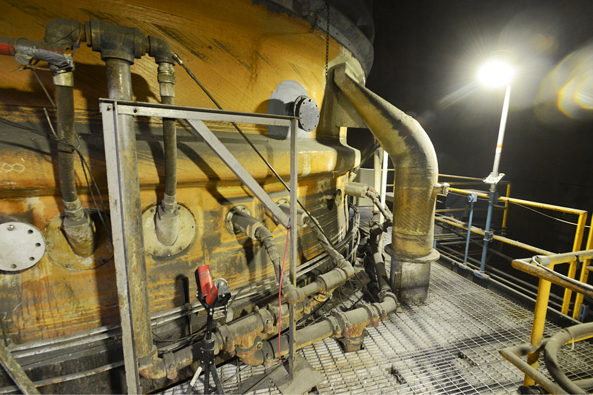
Emissions Monitoring Level 280
300 feet up the stack at the emissions monitoring and sampling level.

Stack Emissions Monitoring Station 281
Meticulously kept records and constant emissions sampling occurs 300 feet up inside the stack at the emissions monitoring and sampling level. Precise sample and chart analysis ensures that Kennecott continually meets or exceeds all guidelines regarding its environmental stewardship.

Hot Metals Building 282
Hot metals building before sunrise. It is in this building that the FS and FC smelter furnaces are housed. The two constructs of pipe and catwalks to the left are built around the two furnace boilers, one for the FS furnace and one for the FC furnace. These boilers recover much of the waste heat that is used to create the steam necessary to generate electricity (among other uses) at the on-site powerhouse steam turbine driven generator. The third construct on the right of the boilers houses the emissions particulate filters (bag houses) which is the first of several steps in the pollution abatement process.

The Mixing Dome
Inside this dome the furnace feed materials, primarily matte, are mixed for proper feed chemistry as determined by control room computers and engineers. Proper chemistry of the materials fed into the furnaces is a critical factor in the smelting process. The need to know the quality of the ore concentrate compounds necessitates constant sampling and lab analysis, many of which are done hourly.
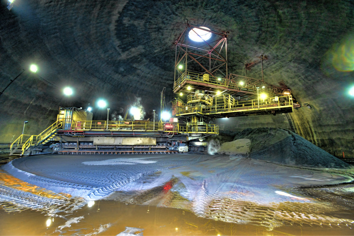
Furnace Feeder Inside The Mixing Dome 286
This feeder, located inside the dome, rotates on a center axis pushing blended furnace concentrate toward the center where it drops onto a conveyor on its way to the FC converting furnace. The top conveyor deposits granulated matte directly from the FS furnace and is one of several ways to introduce blending materials onto the feed pile. Other materials needed to adjust chemistry are deposited directly onto the feed pile using large front end loaders.

Looking Down on a Kress Hauler 288
Taking a Hot Pot to the cooling grounds.

Kress Pots Enveloped In Steam 290

Hot Kress Pots 292
Kress Pots generate a lot of steam during the cooling process.